Go back
 November 16 2026
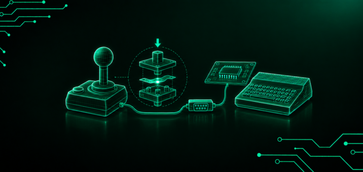
Contacts in retro computers are two-state electrical components: either open or closed. The principle is simple, but the journey from moving a joystick to seeing a character move on the screen passes through multiple layers of hardware, each with its own properties, failure modes and engineering history. Let’s take River Raid on the Atari 65XE as an example. We are flying along a river, with fuel tanks approaching from the right. You push the joystick to the right. On the screen, the aircraft turns. The entire sequence takes a fraction of a second, but before the 6502 processor updates the sprite’s position, the signal has to travel through a contact, a cable, a connector and an I/O chip register. This path is repeatable and deterministic – and, after 40 years, increasingly in need of repair.
A Contact as a System Component, Not a Keyboard Accessory
A contact is a two-state component: an open or closed circuit. Hardware from the 1980s used normally open (NO) contacts, which remain open by default and close when pressed. The contacts operate in a circuit with a pull-up resistor (pull-up to 5 V). When a key or joystick lever is at rest in the neutral position, the resistor maintains a voltage of 5 V at the I/O input – a high state, bit = 1. Pressing the key connects the port pin to ground (GND), the voltage drops to 0 V, and the I/O chip reads a low state (bit = 0 in the register). No press is the default state. A press is an event.
In retro computers, contacts were found in three places: beneath every keyboard key, in each directional joystick switch and beneath the fire button. A failure in any of these locations resulted in a specific, identifiable lack of response – no letter, no movement in a particular direction or no shot. It was not simply that “something wasn’t working”. You knew exactly what had failed and where.
Three Types of Contacts – Three Failure Modes
Hardware from the 1980s was not a monolithic category. Manufacturers used different solutions depending on the device class, expected service life and unit cost. The three dominant designs differ not only in their materials but, above all, in how and when they fail.
| Contact type | Application | Durability | Typical failure |
|---|---|---|---|
| Foil / membrane | ZX Spectrum, Sinclair QL, Atari 65XE and Amstrad CPC keyboards | Low after 30+ years – foils crack and oxidise | Specific keys stop responding due to a break in circuit continuity |
| Microswitch (mechanical) | Cheetah Mach II and Competition Pro joysticks | More than one million mechanical cycles | Dirt on the contact leaves – cleaned with isopropyl alcohol |
| Rubber with a graphite layer | MATT STT joysticks for Amiga 500, Atari and C64 | Long service life, greater than that of metal leaf contacts | Rubber dust accumulates on the contact surface and requires cleaning |
Foil and Membrane Keyboards – Row-and-Column Matrix
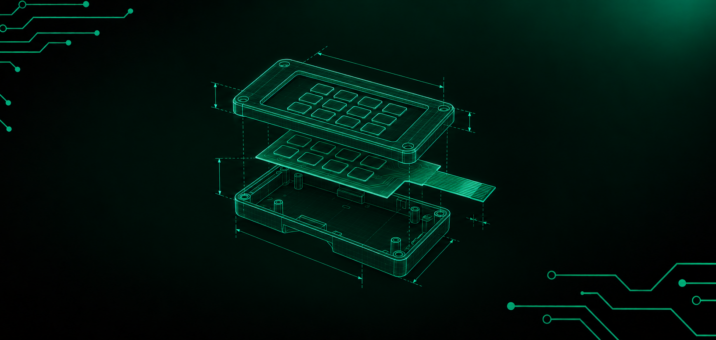
Foil keyboards are based on a row-and-column matrix printed with conductive ink on flexible polyester film. The classic ZX Spectrum (1982) and Sinclair QL used a design with two polyester layers separated by a spacer sheet: the lower film carried the column tracks, while the upper film carried the row tracks. A rubber key mat pressed directly against the upper polyester film, forcing the conductive track printed on it into contact with the track on the lower film and closing the circuit at the intersection of a row and a column. The 3.5 MHz Z80A processor detected the change of state and interpreted it as a key press.
Atari and Commodore keyboards varied in their construction. Alongside membrane designs, manufacturers used PCBs with mechanical switches and hybrid solutions in which the key matrix rested on a dedicated circuit board with a separate scanning controller. This distinction matters today: replacement foil membranes for the ZX Spectrum and Sinclair QL require precise reproduction of the original dual-membrane geometry, whereas faults in Atari 65XE or 800XL keyboards often concern the switch mechanism rather than the foil.
The weakness of foil-based solutions is material ageing. Graphite tracks wear away, films crack after years of repeated flexing, and moisture accelerates oxidation. After 40 years, a typical ZX Spectrum may respond to only some of its keys. This is a characteristic foil failure mode: the entire membrane does not fail at once; a specific location in the matrix stops working.
External Controllers – 9-Pin D-Sub Joysticks, Microswitches and Conductive Rubber
Joysticks with microswitches, such as the Competition Pro by Dynamics, make a loud sound every time they are moved or pressed. The sound comes from the snap-action mechanism: a spring-loaded metal leaf rapidly moves from the open to the closed position when activated. This produces a distinct actuation point and the precision valued by competitive gamers.
Microswitches are more durable than foil contacts. They withstand more than one million mechanical cycles, and their operating characteristics do not drift with age as significantly as those of rubber or foil contacts. When they begin to miss inputs after years of use, the cause is usually dirt on the metal leaves. Cleaning is often enough; immediate replacement is not necessary.
In the late 1980s, a heavily used joystick with metal leaf contacts sometimes lasted only a few months of gaming. Contacts with a graphite layer applied to flexible rubber extended the service life of the device many times over. The Polish company PTH MATT used this technology in its MATT STT joystick, designed for the Amiga 500, Atari 130XE and Commodore 64. Rubber contacts do not produce a click – operation is silent and soft. Their disadvantage is rubber dust, which accumulates on the contact surface after prolonged use and needs to be cleaned away.
Direct Signal Circuits – The Reset Contact on the CPU RESET Line
Alongside keyboard and joystick contacts, retro computers had another special type: the Reset contact. Mechanically, it was identical to the dome beneath the space bar or the metal leaf inside a joystick, but it was connected directly to the processor’s RESET line rather than to the keyboard matrix or joystick port. Pressing it did not send a character to a program; it forced a hard restart of the computer.
On 8-bit Atari computers, Reset was a factory-fitted key on the keyboard. On the ZX Spectrum and Commodore 64, it was usually added as a modification. On the C64, this most often involved routing the CPU RESET line to a button mounted on the case. Electrically, it is the same normally open (NO) contact that converts finger movement into a signal. However, the effect of closing it is radically different. This is a good example of how the function depends not only on the type of contact but also on the circuit to which it is connected.
The Atari 9-Pin D-Sub Port – The Signal Path from Contact to Processor
A joystick connected to an Atari 65XE works with the contacts for retro computers using the Atari 9-pin D-Sub port standard. Each pin has a specific function.
| Pin | Signal | Meaning in the game |
|---|---|---|
| 1 | Up | Move up / jump |
| 2 | Down | Move down / crouch |
| 3 | Left | Move left |
| 4 | Right | Move right |
| 6 | Trigger / Fire | Shoot / action |
| 7 | +5 V power | Power supply for active controllers |
| 8 | GND | Ground (signal reference) |
When the joystick is pushed to the right, a metal leaf inside the joystick touches another leaf, closing the normally open contact. The voltage on pin 4 (Right) drops to 0 V. In 8-bit Atari computers, directional signals (pins 1–4) go to the PORTA and PORTB registers of the PIA chip (6520/6521), not to the POKEY chip. The fire button (pin 6, Trigger/Fire) is connected to the GTIA chip’s TRIG0 line. POKEY serves other functions: keyboard matrix scanning, paddle potentiometers, sound synthesis and the SIO bus. This distinction matters when diagnosing faults: an unresponsive joystick and a silent keyboard are problems involving two different integrated circuits.
The processor reads the input states in a scanning loop – in most 8-bit games, once per screen frame, or 50 times per second in the PAL standard (Europe, including Poland). The maximum time between the contact closing and the game responding is 20 ms. Human perception does not register this delay as noticeable latency.
Keyboard Matrix and Scanning – How the Computer Identifies Keys
8-bit computer keyboards worked differently from joystick ports. Instead of a dedicated pin for each key, they used a row-and-column matrix. In 8-bit Atari computers, the POKEY chip activated the keyboard matrix rows in sequence and read which columns returned a signal, thereby identifying the pressed key. The ZX Spectrum used the ULA chip for the equivalent function. The ZX Spectrum had 8 address lines (half-rows) and 5 data lines (columns), providing a total of 40 keys in an 8×5 matrix. The Atari 65XE had a larger matrix, accommodating function and control keys.
The entire matrix was scanned so quickly that the player did not notice any sequential processing. However, pressing several keys simultaneously could result in false detections (known as ghost keys), especially in the absence of protective diodes in the matrix. Keyboards with a diode at each key eliminated this problem, but were more expensive and less common in 1980s home computers.
The Keyboard as a Controller – The Same Mechanics, Different Mapping
Not every game required a joystick. On the ZX Spectrum, many titles used the Q–W–E–R–T keys or the number keys as directional controls. From an electronic perspective, pressing “Q” was no different from moving a joystick: both closed a circuit and sent a signal to the processor. The only difference was the mapping. The game checked a different register, but the input-reading mechanism was identical.
On Atari and Commodore computers, membrane keyboards were less popular as gaming controllers than joysticks. The D-Sub port offered a clearer response time and avoided the risk of pressing several neighbouring keys at once. In text-based, adventure and puzzle games, however, the keyboard remained the primary interface – and every one of its contacts had to work just as reliably as the directional switches in a joystick.
Why Contacts for Retro Computers Require Ongoing Production
The ZX Spectrum was manufactured from 1982 to 1992. The Atari 8-bit series was produced until 1992. The Amiga 500 was manufactured until 1991. Every one of these computers has now been in existence for more than 30 years. The contacts inside them are either original components approaching the end of their service life or replacement products from manufacturers who have decided to launch a new production run.
The ZX Spectrum polyester membrane is now a niche component. A manufacturer producing it must reproduce the geometry of the original device’s matrix – the ZX Spectrum and ZX Spectrum+ have different contact layouts – select the right conductive ink and maintain production despite low volumes. Mechanical joystick contacts are more readily available because their format is more standardised. Even so, specific versions for particular joystick models require precisely defined contact pressure parameters.
What Does This Look Like at Qwerty?
At Qwerty, we have been working with contacts for retro computers since 1988, treating them as a genuine manufacturing and service challenge. We started by addressing a specific defect: standard foil contacts in the keyboards of 1980s home computers wore out faster than the market could supply replacements.
Today, we continue to manufacture foil contacts for the ZX Spectrum, ZX Spectrum+, Sinclair QL, Atari 65XE, Atari 130XE, Atari 800XL and Amstrad CPC 664. Each module reproduces the original matrix geometry, but the manufacturing technology is completely different from that used in the 1980s. We print conductive tracks using precision screen printing and digital printing on polyester (PET) film selected for its resistance to flexing and moisture. In our own research laboratory, we develop conductive ink formulations – both graphite-based and silver-based – adapting their composition to the requirements of each contact: contact resistance, number of operating cycles and operating conditions. Every contact undergoes 100% electrical inspection before dispatch. We test track continuity, closed-circuit resistance and insulation integrity between adjacent tracks.
The experience gained from producing retro computer contacts now forms the foundation of our membrane and foil keypad manufacturing for industrial and medical electronics. The requirements for CNC machine control panels and buttons on surgical medical devices – resistance to disinfectants, IP-rated sealing and operation across a temperature range of –20°C to +70°C – differ from those of a home computer, but the engineering fundamentals remain the same: a pull-up resistor, a normally open contact and reliable electrical connection with every press.